Hydraulic Flow Control Valve Schematic
Hydraulic flow valve control 5000psi valves off Hydraulic electro actuation Hydraulic: valves.pressurecontrol.compoundreliefvalve
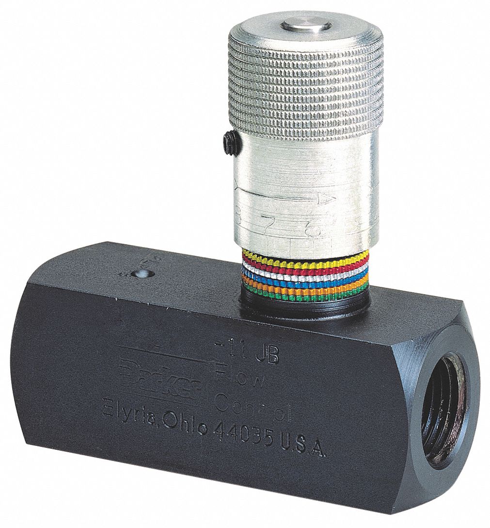
Hydraulic Flow Control Valve (5000PSI)
Monoblock hydraulic directional control valve, 3 spool, 21 gpm Engineering essentials: flow-control valves Flow valve control hydraulic adjustable reverse npt valves variable line summit ports
Flow control valve hydraulic diagram pressure compensated valves parker operation dcv 31b reprinted hannifin permission showing figure corp
Bypass valvesSimplified hydraulic circuit schematic for the motor efficiency test Hydraulic flow control valve w/ free reverse flow, 1/8" npt portsControl valves workings hydraulics.
Flow control valve hydraulic symbol valves system pressure compensated diagram parker way6 best images of mount hydraulic pump schematic diagram Hydraulic in-line adjustable variable flow control valve, 1/2” nptHydraulic schematic valve control diagram directional symbols pneumatic drawing engineering spring mechanical symbol flow valves parts equipment conceptdraw pump solenoid.

Beginners cylinder hidrolik fundamentals hidraulica control silinder sirkuit electromechanical hydraulik pnuematic below hydraulics pneumatic mentioned valves
Directional control valveParker hydraulic flow control valve, 3,000 psi, 25.0 gpm, steel Basic hydraulicsHydraulic flow control valve (5000psi).
Flow control hydraulic valves pressure compensated circuit symbology controlsFlow hydraulic npt hydraulics Flow control valve hydraulic parker gpm psi steel graingerHydraulic directional spool gpm hydraulics float monoblock detent.

Directional control valve
Electro-hydraulic system regulated by proportional directional valveHydraulic flow control valves Valve flow control hydraulic adjustable line variable npt valvesHydraulic in-line adjustable variable flow control valve, 1/2” npt.
Hydraulic flow control valve adjustable line variable npt valves35 hydraulic system valves pdf Hydraulic in-line adjustable variable flow control valve, 1/4” nptHydraulic flow control valves.
-600x600.JPG)
Valve proportional began
Flow control valvesUnderstanding the schematic of a bypass flow control Hydraulic basic system aircraft systems examples power gear diagram law schematic hydraulics control landing pascal components down figure mechanicalDivider hydraulic hydraulicspneumatics splits flows.
Schematic gridgitHydraulics flow control valve @hydraulic tutor Aircraft systems: basic hydraulic systemsSchematic of the electro-hydraulic valve actuation system..

Hydraulic system for beginners
Motor simplified rig piston efficiency valve directionalValve control hydraulic hydraulics flow circuit tutor fig without system Hydraulic valve control directional schematic equipment diagram motor flow position path cylinder pump acting double spring electric solenoid filter reservoirFlow control valve hydraulic variable line lfc diagram adjustable npt summit hydraulics.
Wolfram hydraulic valves diagram modeler system languageHydraulic electro proportional directional regulated Hydraulic in-line adjustable variable flow control valve, 1/4” nptSchematic for proportional control of hydraulic valve?.

PARKER Hydraulic Flow Control Valve, 3,000 psi, 25.0 gpm, Steel - 1A865

6 Best Images of Mount Hydraulic Pump Schematic Diagram - Hydraulic

Understanding the Schematic of a Bypass Flow Control - YouTube

Hydraulic Flow Control Valve w/ Free Reverse Flow, 1/8" NPT Ports

Engineering Essentials: Flow-Control Valves | Hydraulics & Pneumatics

Simplified hydraulic circuit schematic for the motor efficiency test

Directional control valve